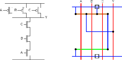
3 Input Nand Gate Schematic
Input nand gate three diagram stick schematic tutorial part Layout nand lab gate nor input xor using schematic gates Reverse-engineering the standard-cell logic inside a vintage ibm chip
NAND Gate Circuit Diagram and Working Explanation
Nand gate cmos inputs spice youspice simulation Nand gate input schematic ibm ring 3 inputs nand gate with cmos
Solved you only have 3-input nand gates and you need a
Nand gate circuit diagram and working explanationNand input gates transcribed Nand gate schematic diagramSatish kashyap: microwind tutorial part 5 : three (3) input nand gate.
Strange chip: teardown of a vintage ibm token ring controllerNand gate diagram circuit ic 74ls00 pinout gates logic circuits chip not input circuitdigest working diagrams explanation electronic using limitations Nand gate decoderSolved: 14.58 consider a four-input cmos nand gate for whi....

Nand cmos input gate four transient consider show response reference dominated which questions solved transcribed text
Schematic nand input reverse logic .
.


Solved: 14.58 Consider A Four-input CMOS NAND Gate For Whi... | Chegg.com

SATISH KASHYAP: MICROWIND Tutorial Part 5 : Three (3) Input NAND gate

3 inputs NAND gate with CMOS - YouSpice
Lab6 - Designing NAND, NOR, and XOR gates for use to design full-adders

Strange chip: Teardown of a vintage IBM token ring controller

NAND Gate Circuit Diagram and Working Explanation

Reverse-engineering the standard-cell logic inside a vintage IBM chip