How To Wire A Bridge Rectifier Diagram
Simple bridge rectifier circuit Diagram rectifier bridge wiring circuit wave applications Zener bridge rectifier circuit diagram
Bridge Rectifier Wiring Diagram - Wiring Diagram Schema
How a bridge rectifier works Full wave bridge rectifier circuit working and applications Rectifier circuit circuits current alternating relay convert
Rectifier bridge pcb diode diodes circuitdigest
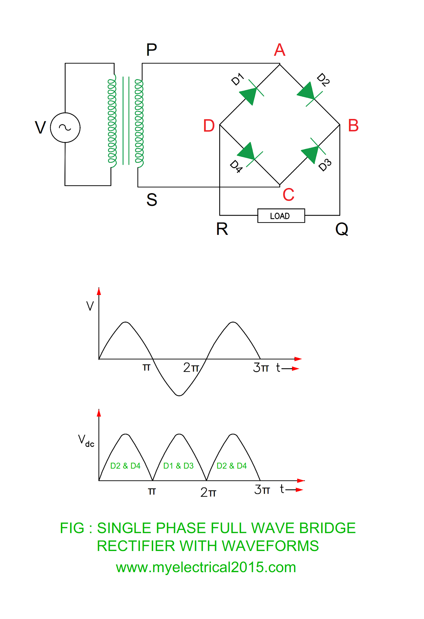
Rectifier machinistDiode bridge rectifier Diode bridge rectifier electrical4uFull wave bridge rectifier operation.
Rectifier wave cycleRectifier resistor derf Rectifier wave bridge full operation half animation working input current positive gif diodes reverse cycle forward biased during d3 d4Rectifier capacitor resistor transcription electrical.

Electrical revolution
Pinout rectifier bridge datasheet 1000v 50a manufacturer dimensions supportBridge zener rectifier circuit diagram diagramz Bridge rectifier wiring diagramSimple bridge rectifier circuit.
Kbpc5010 1000v 50a bridge rectifier dimensions, pinout, and[solved] only problem 2! repeat problem 1 for the full-wave bridge 13+ bridge rectifier schematicRectifier circuits.

Rectifier circuit bridge diagram wave full working details
Full wave bridge rectifier circuit .
.

![[Solved] Only problem 2! Repeat Problem 1 for the full-wave bridge](https://i2.wp.com/www.coursehero.com/qa/attachment/3974530/)
[Solved] Only problem 2! Repeat Problem 1 for the full-wave bridge

KBPC5010 1000V 50A Bridge Rectifier Dimensions, Pinout, and

Simple Bridge Rectifier Circuit

Diode Bridge Rectifier | Electrical4U

Simple Bridge Rectifier Circuit

13+ Bridge Rectifier Schematic | Robhosking Diagram

Full Wave Bridge Rectifier Circuit Working and Applications
Electrical Revolution

Bridge Rectifier Wiring Diagram - Wiring Diagram Schema